Wind Load on Parapets

ASCE 7 has multiple methods for calculating wind loads on a Parapet. In the context of a building design, a parapet is a low protective wall along the edge of a roof. It could be used to hide equipment on the roof and it can also serve as a barrier to provide some protection from a person easily falling off of the roof. There are two aspects of the design: the consideration of the parapet from a structural integrity standpoint, by considering it as a Main Wind Force Resisting System (MWFRS) and also analyzing the cladding on the parapet as Components and Cladding (C&C). This article explains how to follow ASCE 7-16 when calculating wind loads on a building parapet.
MWFRS Directional Procedure (Ch 27 Part 1)
In Chapter 27 Part 1 of ASCE 7-16, it covers the MWFRS design following the directional procedure. The wind load on parapet is determined in Section 27.3.4. This is best illustrated with an example.
ASCE 7-16, 120 mph, Exp. C, Category II
Enclosed Building with Flat Roof
Building Roof Height = 30 ft
Length = 100 ft
Width = 50 ft
Solid Parapet = 3 ft Tall
Table 26.11-1 for Exp C –> zmin = 15 ft, zg = 900 ft, Alpha = 9.5
z = 30 ft + 3 ft (Top of Parapet)
Kz=2.01*(33 ft / 900 ft)^(2/9.5) = 1.002
G = 0.85 (Rigid Structure)
Kzt = 1.0 (No topographic feature)
Ke = 1 (Sea Level)
Kd = 0.85 (Building MWFRS per Table 26.6-1)
Calculate Pressure at top of Parapet:
qp = qz = 0.00256*1.002*1*0.85*1*120^2 = 31.4 psf
From Section 27.3.4 it is given that GCpn = +1.5 for windward parapet, and -1.0 for leeward parapet. Using this in combination with equation 27.3-3, the pressure on the parapet is as follows:
Windward: Pp_windward = 31.4 psf * 1.5 = 47.1 psf
Leeward: Pp_leeward = 31.4 psf * -1 = -31.4 psf
Total: Pp_total = 47.1 + 31.4 = 78.5 psf
This same problem has been worked using the MecaWind software, and the results from that analysis are shown below (MecaWind input file following this example can be downloaded here).

MWFRS Directional Simple Diaphragm (Ch 27 Part 2)
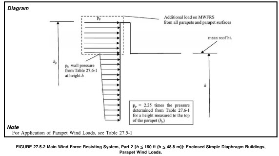
In Chapter 27 Part 2, it covers MWFRS design based upon the directional procedure for a Simple Diaphragm building. The wind load on the parapet is addressed in Section 27.5.2, which states that the net parapet pressure shall be 2.25 times the wall pressure tabulated per Table 27.5-1 for L/B = 1.0. This net pressure accounts for both the windward and leeward pressures and would be comparable to the “total” pressure calculated in the example above using Ch 27 Part 1.
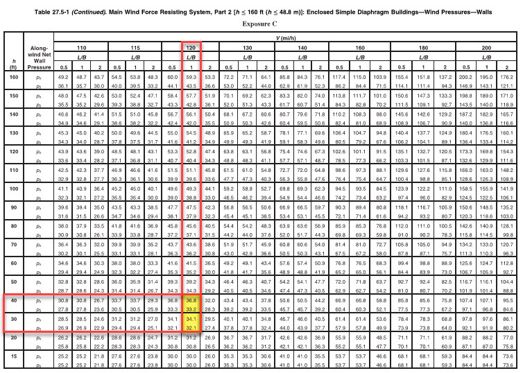
Referring to Table 27.5-1 for Exposure C, 33 ft, L/B = 1 and 120 mph, we get a wall pressure of 34.91 psf using interpolation. Then we must multiply this by 2.25 to get the parapet pressure.
Pp = 2.25*34.91 = 78.55 psf

MWFRS Envelope Procedure (Ch 28 Part 1)
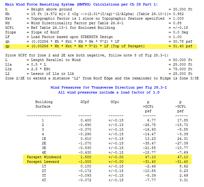
The MWFRS Envelope procedure is covered by Chapter 28 Part 1, and the parapet calculation is addressed in Section 28.3.2. The procedure is identical to that used for the Directional Procedure in Ch 27 Part 1, and so refer to those calculations previously presented. The wind load on the parapet is calculated as follows:
Windward: Pp_windward = 31.4 psf * 1.5 = 47.1 psf
Leeward: Pp_leeward = 31.4 psf * -1 = -31.4 psf
Total: Pp_total = 47.1 + 31.4 = 78.5 psf
This problem was analyzed using MecaWind, and the results are shown below (MecaWind input file for this problem can be downloaded here).
MWFRS Envelope Simple Diaphragm (Ch 28 Part 2)
The MWFRS Envelope procedure is covered by Chapter 28 Part 2; however, there are no provisions in this section that address parapets.
C&C Simplified Buildings 60 ft [18.3m]<h<=160 ft [48.8m] (Ch 30 Part 4)
There are only two sections in Chapter 30 that address Components and Cladding pressures for parapets, Chapter 30 Part 4 and Chapter 30 Part 6. If you are following Part 4 for your design, then you use the parapet criteria from Part 4; however, for all other C&C methods use Part 6 for the parapet C&C design.
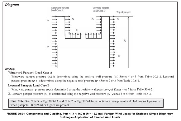
In Part 4, the parapets are governed in Section 30.6.3. This section directs the designer to obtain pressures from Table 30.6-2 and consider two load cases:
Load A – Apply positive wall pressure to front of parapet while applying negative edge or corner zone roof pressures to the back of parapet.
Load B – Apply positive wall pressure to the back of the parapet while applying negative wall pressure to the front of the parapet.
Using the same example as previously considered, let’s now add parapet component and cladding:
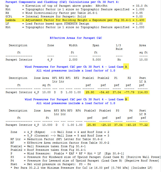
Cladding Width = 2 ft, Cladding Span = 5 ft
Effective Area = 2×5 = 10 sq ft
qp = 31.4 psf (taken from earlier calculations)
Referring to Table 30.6-2, since the height is <= 60 ft the table refers us to Fig 30.4-1.
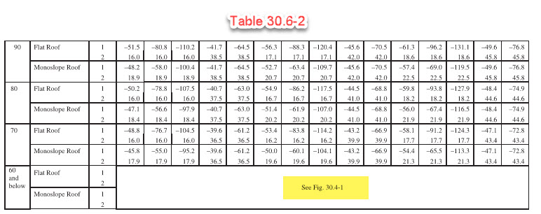
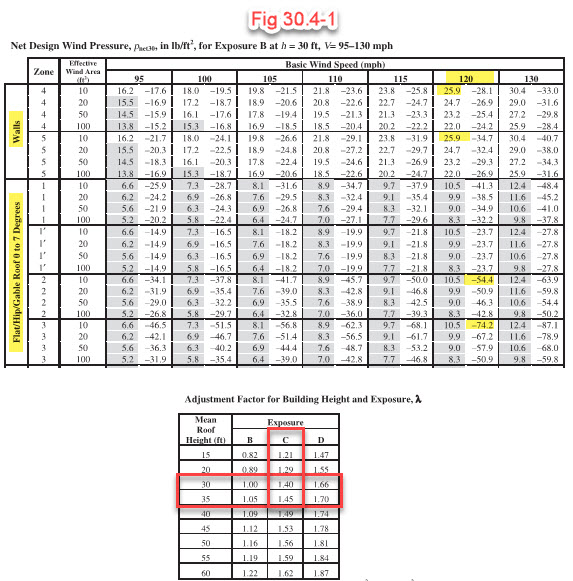
For a parapet height of 33 ft, the Lambda is 1.43. Using this and the values found in Fig 30.4-1, the following are calculated:
Load Case A:
Ptable1 = 25.9 psf (Positive for Zone 4)
Ptable2 = -54.4 psf (Negative for Zone 2)
Lambda = 1.43 (Fig 30.4-1)
RF = 1.0 (Table 30.6-2 since Eff Area = 10 sq ft, same for everything)
Kzt = 1 (No topographic Feature)
P1 = 25.9 psf * 1.43 * 1.0 * 1.0 = 37.04 psf (Windward Pressure)
P2 = -54.4 psf * 1.43 * 1.0 * 1.0 = -77.79 psf (Leeward Pressure)
Pnet = 37.04 + 77.79 = 114.83 psf
Load Case B:
Ptable1 = 25.9 psf (Positive for Zone 4)
Ptable2 = -28.1 psf (Negative for Zone 4)
Lambda = 1.43 (Fig 30.4-1)
RF = 1.0 (Table 30.6-2 since Eff Area = 10 sq ft, same for everything)
Kzt = 1 (No topographic Feature)
P3 = 25.9 psf * 1.43 * 1.0 * 1.0 = 37.04 psf (Windward Pressure)
P4 = -28.1 psf * 1.43 * 1.0 * 1.0 = -40.18 psf (Leeward Pressure)
Pnet = 37.04 + 40.18 = 77.22 psf
C&C All Other Buildings (Ch 30 Part 6)
All buildings falling within the criteria of Ch 30 Part 4 should follow Part 4, and all other buildings will follow Ch 30 Part 6.
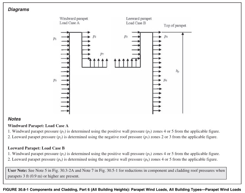
In Part 6, the parapets are governed in Section 30.8. This section directs the designer to obtain pressures from various figures depending upon the specifics being considered. As shown above, Part 4 is complicated, and things don’t get much easier with Part 6. Neither Part 4 nor Part 6 are very easy to interpret and apply to a given situation.
Load A – Apply positive wall pressure to front of parapet while applying negative edge or corner zone roof pressures to the back of parapet.
Load B – Apply positive wall pressure to the back of the parapet while applying negative wall pressure to the front of the parapet.
Using the same example as previously considered, lets now add parapet compent and cladding:
Cladding Width = 2 ft, Cladding Span = 5 ft
Effective Area = 2×5 = 10 sq ft
qp = 31.4 psf (Taken from earlier calculations)
For the wall GCp coefficients we refer to Figure 30.3-1 and since the roof is flat then for roof coefficients we refer to Fig 30.3-2A.
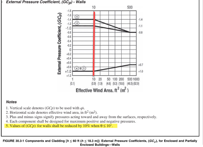
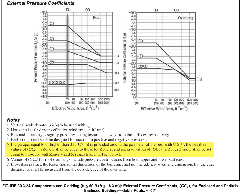
Referencing Fig 30.3-1, note 5 indicates that since our roof slope <= 10 Deg then the GCp values taken from the chart are reduced by 10%. With this in mind, the GCp factors are as follows:
Zone 4 Positive GCp = 1.0 * 0.9 = 0.9
Zone 4 Negative GCp = -1.1 * 0.9 = -0.99
If we reference Figure 30.3-2A, then note 5 indicates that since we have a parapet at least 3 ft tall and the slope is <= 7 Deg then the following is true:
Negative GCp in Zone 3 shall be equal to Zone 2. In this example we are only considering Zone 4, which in turn references Zone 2 for the negative leeward coefficient; therefore, this note doesn’t apply in our example, but it would if we were using zone 5.
Zone 2 Negative GCp = -2.3
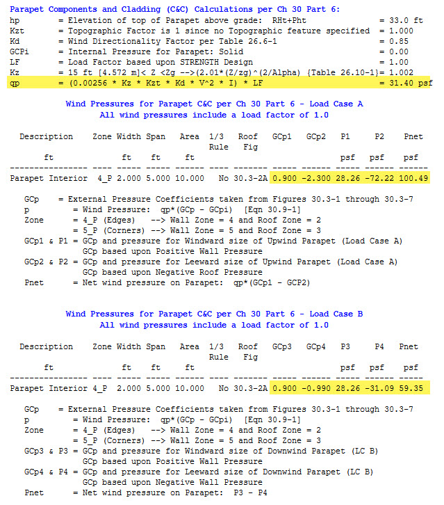
Taking all of this into account, we get the following pressures for Load Cases A and B:
Load Case A:
P1 = 31.4 psf * (0.9 – 0) = 28.26 psf (Positive GCp for Zone4)
P2 = 31.4 psf * (-2.3 – 0) = -72.22 (Negative GCp for Zone 2)
Pnet = 28.26 psf + 72.22 = 100.49 psf
Load Case B:
P3 = 31.4 psf * (0.9 – 0) = 28.26 psf (Positive GCp for Zone4)
P4 = 31.4 psf * (-0.99 – 0) = -31.09 (Negative GCp for Zone 4)
Pnet = 28.26 psf + 31.09 = 59.35 psf
Conclusions:
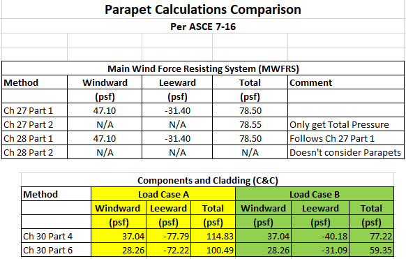
In the Main Wind Force Resisting System (MWFRS), we calculated the pressures using all 3 methods, and we found that the results agreed very well. Chapter 27 Part 1 and Chapter 28 Part 2 are basically identical, so they should result in the same pressures. Chapter 27 Part 2 is a simplified method that only calculates the total pressure on the parapet, but that pressure matched nearly identical to the other methods used.
The Components and Cladding (C&C) only have two options, and Chapter 30 Part 4 produces higher values than does Chapter 30 Part 6.
Meca is admittedly in the business of selling software, but we feel this article should show how much time and aggravation can be saved by using the MecaWind software for these types of calculations rather than calculating them by hand. Granted, it’s not a bad idea to check the calculations performed by the software at least once, to verify to yourself that they are correct; however, after going through these examples I personally hope that it’s a long time before I have to work them manually again. It’s a very tedious process and it’s very easy to make a mistake.

